To totally unlock this section you need to Log-in
Login
As devices are added to a small network, more switch ports are needed to connect those devices to the network. At some point, additional switches may be added to accommodate that growth. Ideally, those switches will be connected to each other, allowing for connectivity between devices.
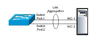
Link aggregation, or LAG is a method of using two Ethernet ports in parallel to provide trunking and network fault tolerance. Link aggregation with trunking feature enhances connection speed beyond the limits of any one single cable or port.
Link Aggregation (LAG)
The improved transmission performance is best observed in environments where multiple-client connections are present. The redundancy also creates higher link availability and avoids possible disruption occurrences.
Adding unmanaged switches is a cheap and easy strategy, but a limited one. Unmanaged switches may be susceptible to loops (no Spanning Tree support), have no broadcast control (no VLAN support), and lack support for features such as Quality of Service (QoS) and Link Aggregation or Trunking.
Managed switches provide many advantages for a growing network, including support for VLANs, QoS, and Trunking. In this article, we're going to describe how to set up Link Aggregation between two managed switches to provide connectivity, redundancy, and expanded bandwidth.
LAG example
We're going to set up Link Aggregation between two gigabit switches: an 8 port Linksys SRW2008; and a 16 port Netgear GS716GT, shown in Figures 1 and 2 below. We covered both switches here a while back. Link Aggregation can also be set up with multiple NICs between a server and a switch.
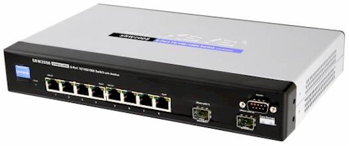
Figure 1: Linksys SRW2008
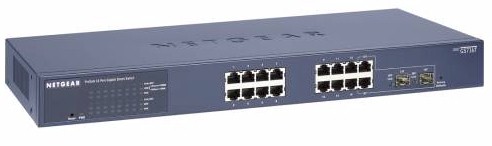
Figure 2: Netgear GS716GT
Link Aggregation is also referred to as Port Trunking, Port Teaming, Ethernet Trunking, and Link Bundling. Cisco has a a multi-port proprietary technology known as EtherChannel. All refer to the same concept; multiple ports acting as a single connection between network devices.
The key to setting up Link Aggregation between different brands is ensuring they both support the IEEE standard 802.3ad.
The value to Link Aggregation is that the two switches will treat multiple ports configured in a Link Aggregate Group (LAG) as a single trunk, providing increased total bandwidth, as well as redundancy. If two ports are configured as a single LAG between two gigabit switches, there will be two Gbps total bandwidth between the two switches (1 Gbps in each direction).
Further, if one of the links were to fail, the connection would continue ,but with only 1 Gbps of bandwidth. Note that when connecting switches in different areas of a building with LAGs, a best practice is to run the cables over different paths to minimize the chances of both cables getting cut simultaneously.
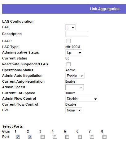
Setting up a LAG on my two switches was a simple task. You have to connect Ethernet cables to ports 1 and 2 on these two switches, then apply the following configuration: on the Linksys, navigate to Port Management > Link Aggregation > LAG 1 > Detail then select ports 1 and 2 as shown in Figure 3 below.
How to set up switch Link Aggregation (LAG)
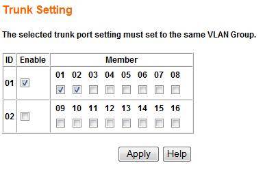
For the Netgear, click Trunking and then selected ports 1 and 2 as shown in Figure 4 below:
How to set up switch Link Aggregation (LAG)
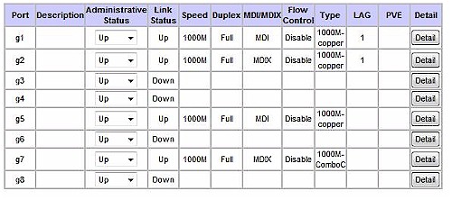
Once complete, both the Linksys and Netgear indicated that ports 1 and 2 were now functioning as a common trunk. As you can see in Figure 5, the Linksys switch shows that ports g1 and g2 are members of LAG 1. Further inspection in the Linksys VLAN menu shows these two ports no longer as members of any specific VLAN, which is expected now that they are providing trunking between switches.
How to set up switch Link Aggregation (LAG)
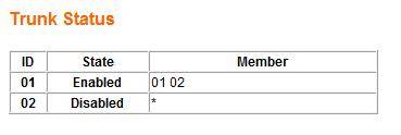
Figure 6 below shows the status of ports 1 and 2 on the Netgear switch. Although a more basic display, it is showing that the switch considers both ports 1 and 2 to be a single trunk, in this case Trunk ID 1.
How to set up switch Link Aggregation (LAG)
Try testing Link Aggregation from a laptop connected to the Linksys running a continuous ping to the management interface of the Netgear. Then disconnect one of the links between the Linksys and the Netgear and observe the output of the ping.
Disconnecting one link will cause a single ping to fail, which quickly restore as the ping moved to the second path.
This simple test also illustrates an important concept regarding Link Aggregation. A single data flow between two end points will travel over a single link in the LAG. Even though there are two or more paths between the two switches, each individual data flow can only use one path in order to maintain proper data sequencing. A data flow will failover almost instantly to a second path when Link Aggregation is deployed, but can't use both simultaneously.
A final interesting aspect about a LAG is it doesn't increase throughput for individual data flows. Each data flow is limited to the bandwidth of a single link in the LAG. In a LAG with two or more 1 Gbps links, the best throughput an individual data flow will see is 1 Gbps. The real value of LAG is in increasing total (or aggregate) throughput between devices.
Usage
Network backbone
Link aggregation offers an inexpensive way to set up a high-speed backbone network that transfers much more data than any one single port or device can deliver. Link aggregation also allows the network's backbone speed to grow incrementally as demand on the network increases, without having to replace everything and buy new hardware.
Most backbone installations install more cabling or fiber optic pairs than is initially necessary, even if they have no immediate need for the additional cabling. This is done because labor costs are higher than the cost of the cable, and running extra cable reduces future labor costs if networking needs change. Link aggregation can allow the use of these extra cables to increase backbone speeds for little or no extra cost if ports are available.
Order of frames
When balancing traffic, network administrators often wish to avoid reordering Ethernet frames. For example, TCP suffers additional overhead when dealing with out-of-order packets. This goal is approximated by sending all frames associated with a particular session across the same link.
The most common implementations use L3 hashes (i.e. based on the IP address), ensuring that the same flow is always sent via the same physical link.
However, depending on the traffic, this may not provide even distribution across the links in the trunk. It effectively limits the client bandwidth in an aggregate to its single member's maximum bandwidth per session.
Principally for this reason 50/50 load balancing is almost never reached in real-life implementations; around 70/30 is more usual. Advanced switches can employ an L4 hash (i.e. using TCP/UDP port numbers), which will bring the balance closer to 50/50 as different L4 flows between two hosts can make use of different physical links.
Maximum throughput
Multiple switches may be utilized to optimize for maximum throughput in a multiple network switch topology, when the switches are configured in parallel as part of an isolated network between two or more systems. In this configuration, the switches are isolated from one another.
One reason to employ a topology such as this is for an isolated network with many hosts (a cluster configured for high performance, for example), using multiple smaller switches can be more cost effective than a single larger switch. If access beyond the network is required, an individual host can be equipped with an additional network device connected to an external network; this host then additionally acts as a gateway.
The network interfaces 1 through 3 of computer cluster node A, for example, are connected via separate network switches 1 through 3 with network interfaces 1 through 3 of computer cluster node B; there are no inter-connections between the network switches 1 through 3.
The linux bonding driver mode typically employed in configurations of this type is balance-rr; the balance-rr mode allows individual connections between two hosts to effectively utilize greater than one interface's bandwidth.
Use on network interface cards
NICs trunked together can also provide network links beyond the throughput of any one single NIC. For example, this allows a central file server to establish an aggregate 2-gigabit connection using two 1-gigabit NICs teamed together. Note the data signaling rate will still be 1Gbit/s, which can be misleading depending on methodologies used to test throughput after link aggregation is employed.
Microsoft Windows
Microsoft Windows does support native link aggregation starting from Windows Server 2012. For the previous Windows Server versions however, some manufacturers provide software for aggregation on their multiport NICs at the device driver layer. Intel, for example, has released a package for Windows called Advanced Networking Services (ANS) to bind Intel Fast Ethernet and Gigabit cards.
Nvidia also supports "teaming" with their Nvidia Network Access Manager/Firewall Tool.
Hewlett-Packard also has a teaming tool for HP branded NICs which will allow for non-etherchanneled NIC teaming or which will also support several modes of etherchannel (port aggregation) including 802.3ad with LACP.
In addition there is a basic layer-3 aggregation (available at least from Windows XP SP3), that allows servers with multiple IP interfaces on the same network to perform load balancing, and home users, with more than 1 internet connection, to increase connection speed by sharing the load on all interfaces.
Broadcom offers advanced functions via Broadcom Advanced Control Suite (BACS) via which the teaming-functionality of BASP (advanced server program) are available offering 802.3ad static lags, LACP and "smart teaming" which doesn't require any configuration on the switches to work.
It is possible to configure teaming with BACS with a mix of NIC's from different vendors as long as at least one of them is Broadcom and the other NIC's do have the required capabilities to create teaming.
 |  |