To totally unlock this section you need to Log-in
Login
VLANs or virtual LANs, are a great tool to segment LANs without having to build a complex and costly network infrastructure. Even with only a unique switch you can build a network with multiple broadcast domains.
Other advantages of adopting VLANs are scalability, network performance, improved efficiency and better security.
In this article we will see to implement VLANs by using HP 1910 Switch Series. We’ll show you how to segment your LAN into VLANs with these switches.
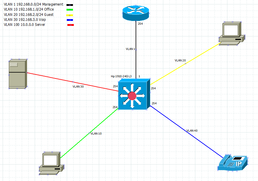
Before starting, here is the scheme of the network we are going to build. We are using a HP 1910-24G switch with inter-VLAN routing capabilities. A switch operating at the third layer of the ISO/OSI model:
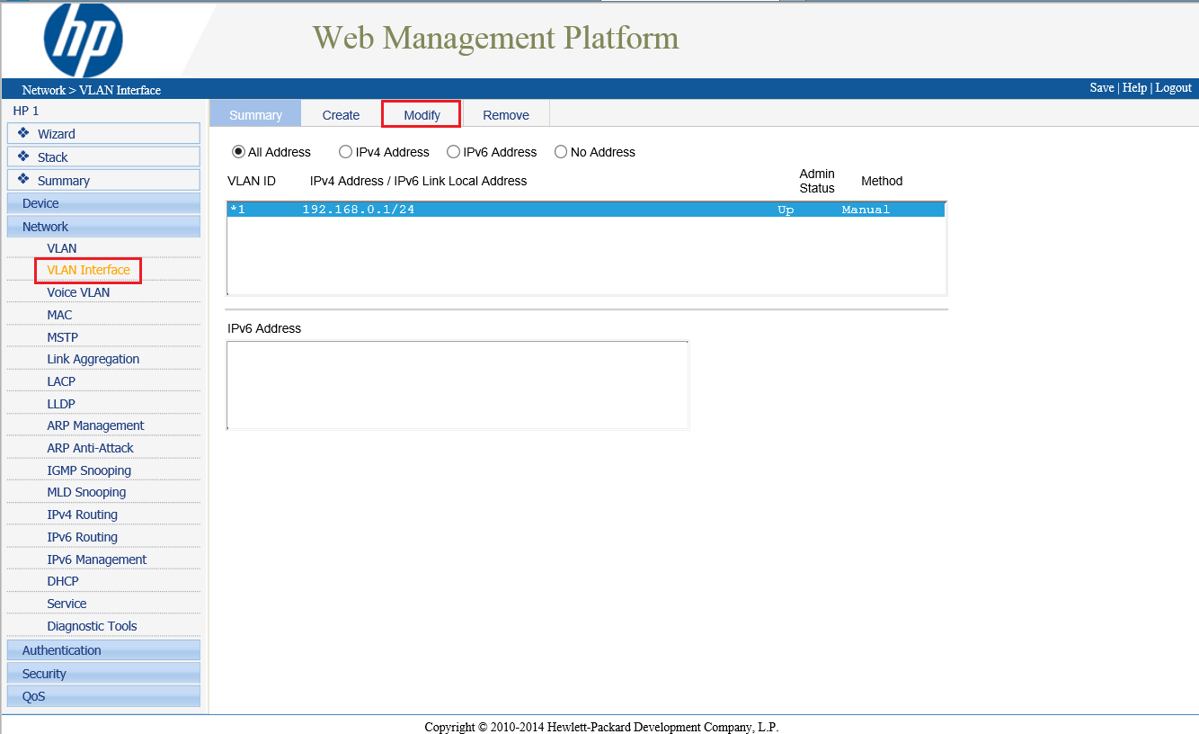
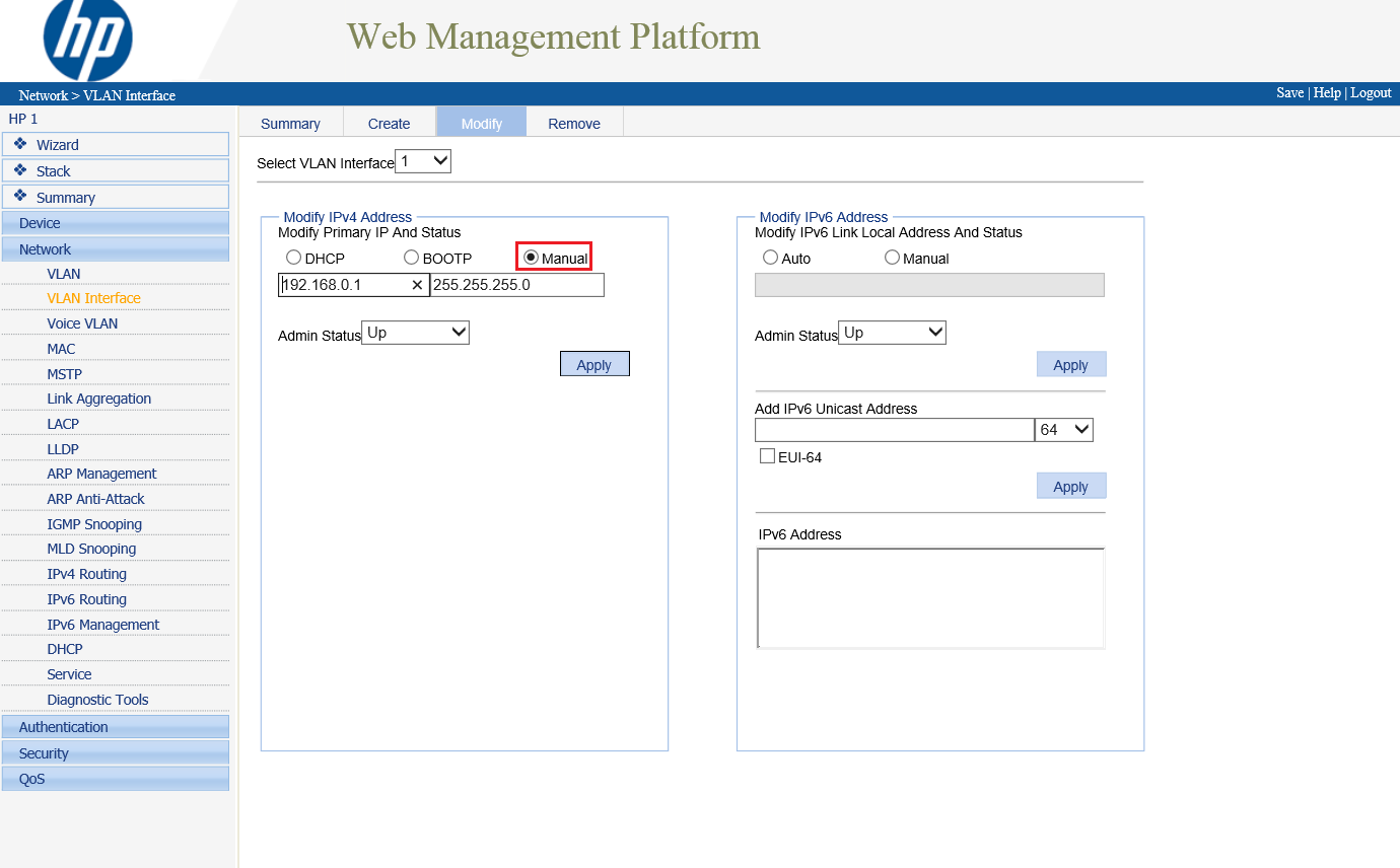
The first step is to access your switch and configure the management address (of the switch itself):
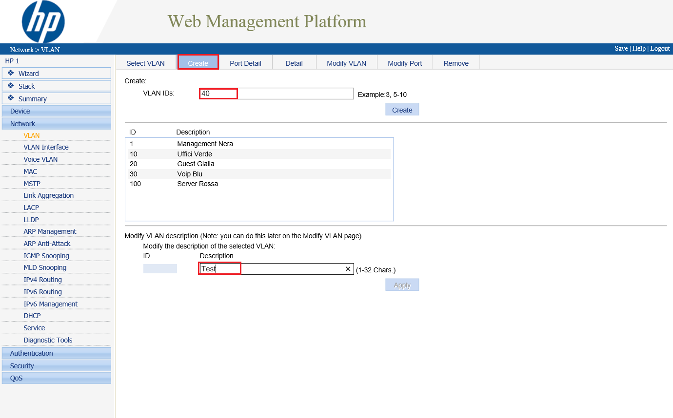
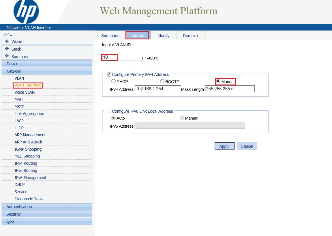
Now let’s create the VLANs defined in our project. Every VLAN has an ID and a description:
In order to allow all the connected devices to interact and access the Internet, you need to configure the L3 routing capabilities of the switch. Define an IP address for each VLAN interface, this address will be specified as Default Gateway in the network configuration of each device (PC, tablet, smartphone, printer, etc..) connected to the related VLAN:
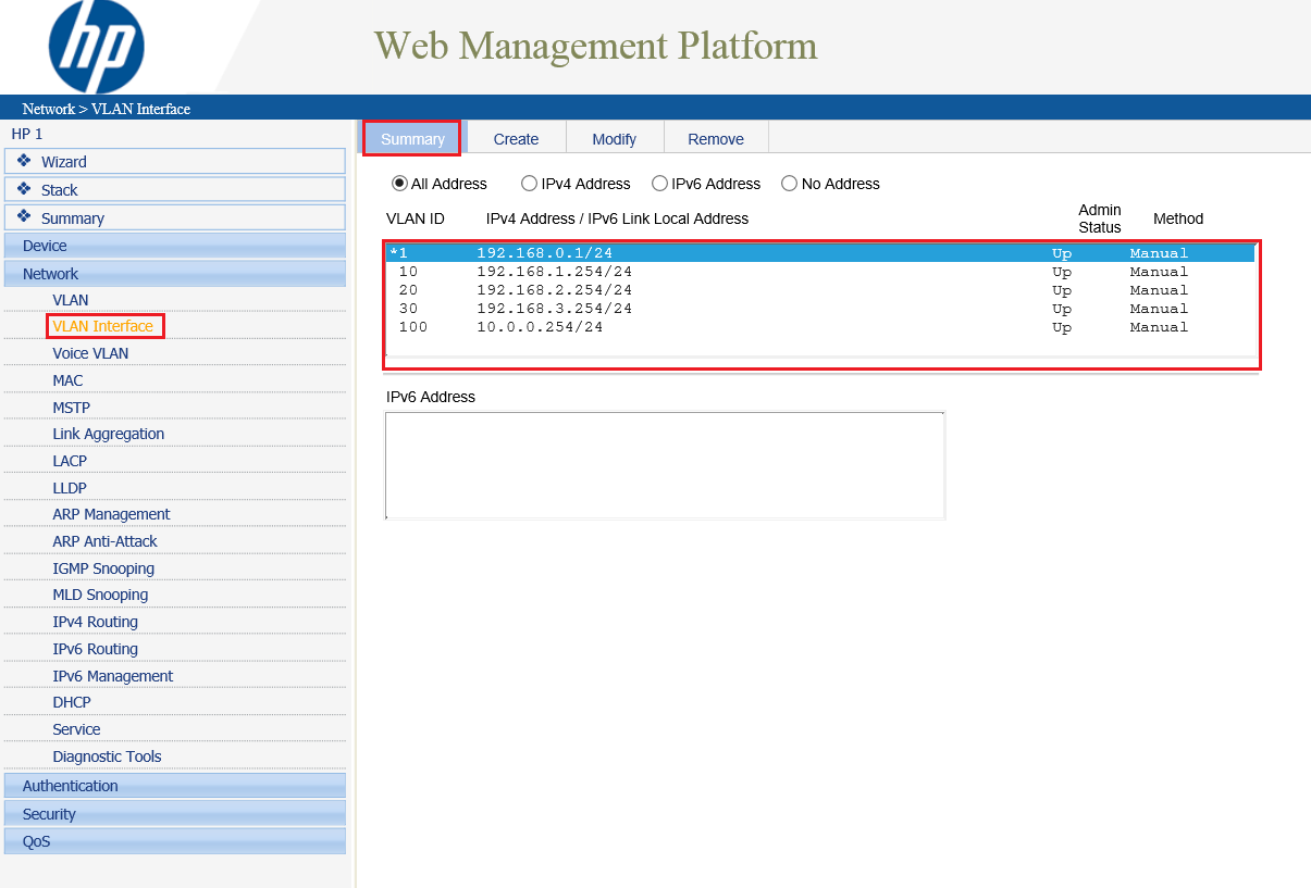
You can check the addresses of the VLAN interfaces from the Summary tab:
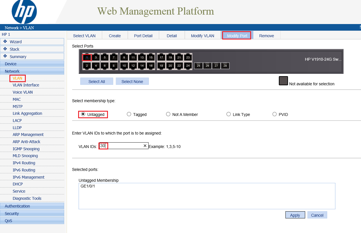
It’s time to assign a physical port to each VLAN. In the following screenshot we are assigning port 1 to the VoIP VLAN (ID 30). In order to assign the physical port (untagged) it must be configured in access mode:
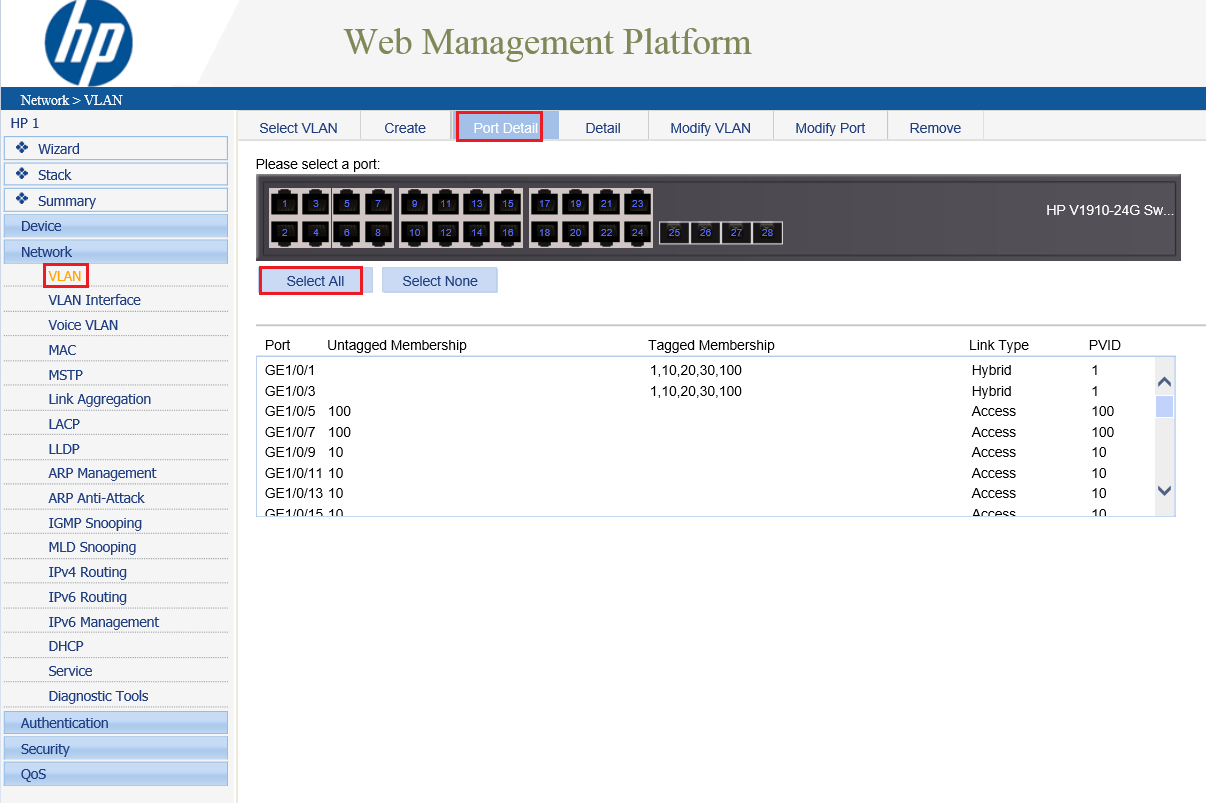
You can also check the configuration of each port from the Port Detail tab:
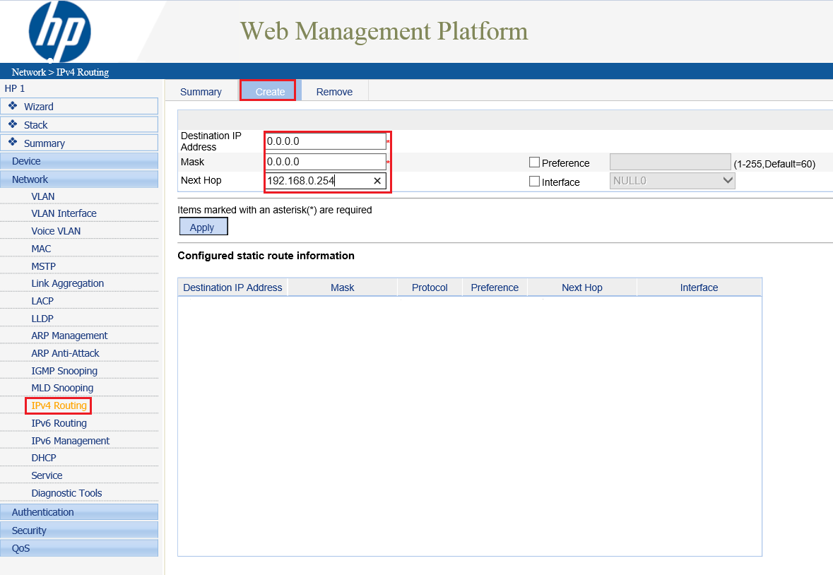
To let all the subnets related to each VLAN access the Internet you need to configure the L3 switch. Define a last resort gateway (or default route) specifying as Next Hop the router managing the Internet traffic:
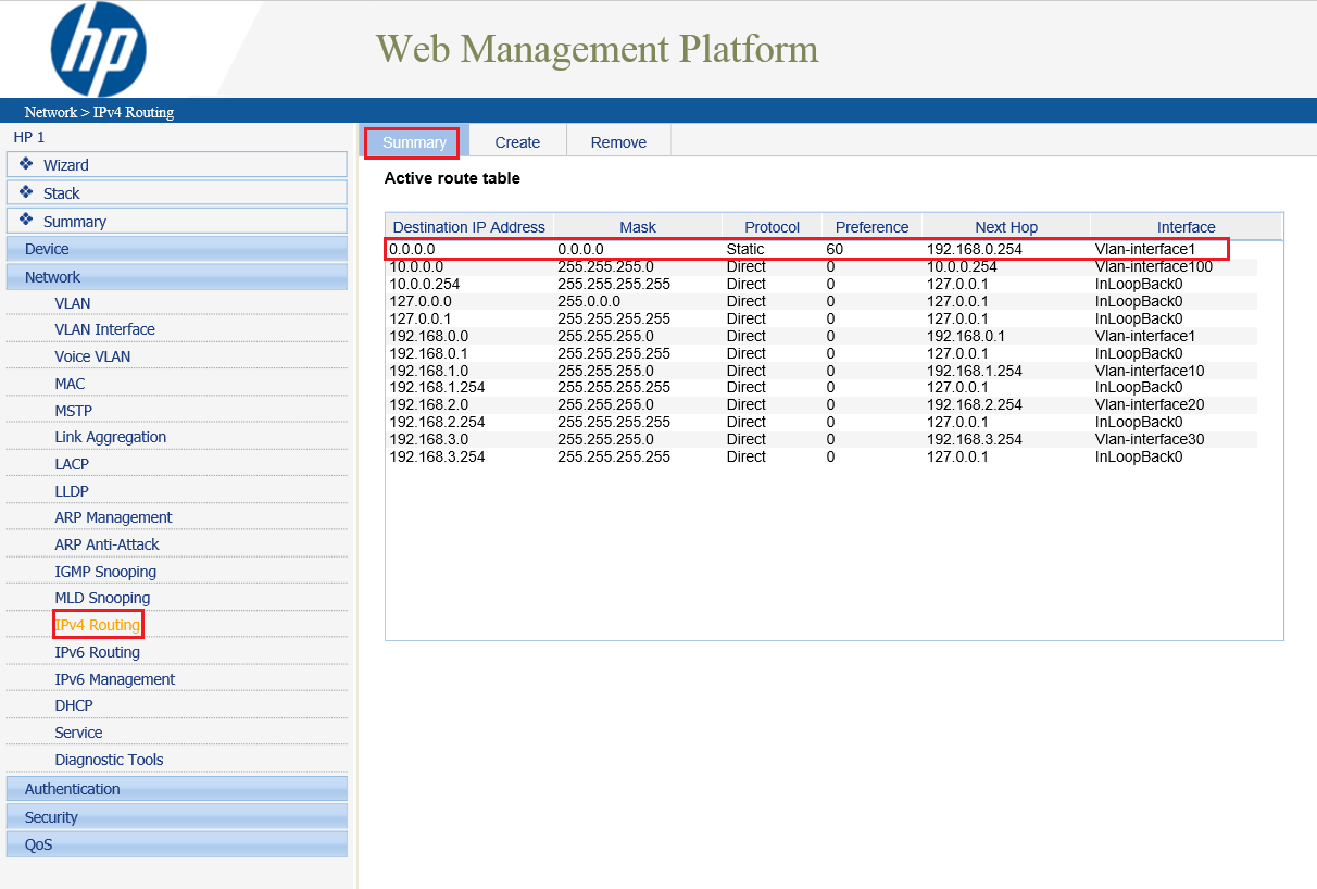
From the Summary tab you can check the routing configuration:
It’s also necessary to configure the Internet router with static routes. These routes will direct traffic to the assigned VLANs. You need to specify the address of the switch as Next Hop.
InterVLAN Routing
Suppose we have made 2 logical group of devices (so two VLANs) named Sales and Finance. If a device in Sales department wants to communicate with a device in Finance department, inter VLAN routing has to be performed. These can be performed by either router or layer 3 switches.
Switch Virtual Interface (SVI)
SVI is a logical interface on a multilayer switch which provides layer 3 processing for packets to all switch ports associated with that VLAN. A single SVI can be created for a VLAN. SVI for layer 3 switch provides both management and routing services while SVI on layer 2 switch provides only management services like creating vlans or telnet/SSH services.
Process of Inter Vlan Routing by Layer 3 Switch
The SVI created for the respective VLAN acts a default gateway for that Vlan just like the sub-interface of the router (in the process of Router On a stick). If the packet is to be delivered to different VLAN i.e inter Vlan Routing is to be performed on layer 3 switch then first the packet is delivered to layer 3 switch and then to destination just like in the process of router on a stick.
Configuration
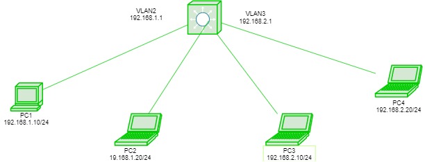
Here is a topology in which we have a layer 3 switch connected to host devices namely PC1, PC2, PC3, PC4.
The hosts PC1, PC2 will be in Vlan 10 and PC3, PC4 will be in Vlan 20. Giving IP address to all hosts as follows: PC1-192.168.1.10/24, PC2-192.168.1.20/24, PC3 – 192.168.2.10/24, PC4-192.168.2.20/24.
Now creating vlans on layer 3 switch namely vlan 2 on the switch ports fa0/1, 2 and fa0/3, 4 for vlan 3.
Switch# vlan 2
Switch# vlan 3
Switch# int range fa0/1-2
Switch# switchport access vlan 2
Switch# int range fa0/3-4
Switch# switchport access vlan 3
Now creating SVI for vlan 2 giving it IP address 192.168.1.1/24 and SVI for vlan 3 giving IP address 192.168.2.1/24:
Switch# ip routing
Switch# int vlan 2
Switch# ip address 192.168.1.1 255.255.255.0
Switch# int vlan 3
Switch# ip address 192.168.2.1 255.255.255.0
Now if we will try to ping PC1 to PC4.
The packet is first delivered to switch then to the destination. As the destination is present in other networks, the packet will be first delivered to switch which has a SVI for both vlans (acts as gateway).
Advantages
In router on a stick method, both switch and router are needed but while using layer 3 switch, a single switch will perform inter-vlan routing as well as the layer 2 functions (VLAN), therefore this method is cost effective and also less configuration is needed.
Access and trunk ports
In VLAN there are some important port configuration. Switch ports are layer 2 interfaces which are used to carry layer 2 traffic. A single switch port can carry single VLAN traffic whether it is an access port or trunk port. Frames are handled differently according to the type of link they are traversing.
NOTE: All switch ports are assigned VLAN 1 by default (VLAN 1 cannot be modified or deleted).
There are 2 different types of ports in a switched environment:
Access ports
These switch ports belongs to carry the traffic of only one VLAN. By default, it will carry the traffic of native vlan (VLAN 1) .If the switch ports are assigned as access ports then it can be considered as the switch ports belongs to a single broadcast domain. Any traffic arriving on these switch ports are considered as it belongs to the VLAN assigned to the port.
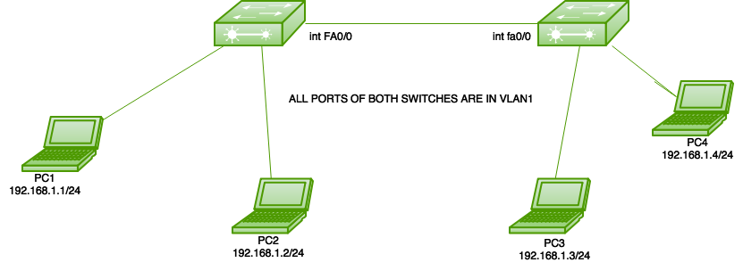
Here is a simple topology in which 2 switches are connected and only the default VLAN (VLAN 1) is configured on both switches i.e all the switch ports of both switches belongs to single broadcast domain.
Now, note that the link between the switches has to be configured as an access port because only a single VLAN (VLAN 1) data has to be exchanged. Now after assigning IP address to PC1-12.168.1.1/24, PC2-192.168.1.2/24, PC3-192.168.1.3/24, PC3-192.168.1.4/24, user shall configure the link between 2 switches as access port.
Switch1(config)#interface fa0/0
Switch1(config-if)#switchport mode access
Here, there is no need to assign VLAN to the ports as all the switch ports on both switches are configured as VLAN 1 by default.
Trunk ports
These switch ports belongs to and carry the traffic of more than one VLAN. This is a great advantage as to carry the traffic of group of VLAN, a single switch port can be used. These are of great use if user wants to exchange traffic between more than one switches having more than one vlan configured.
To identify traffic belongs to which VLAN, VLAN identification method (802.1q or ISL for Cisco) are used. Also, to carry traffic between more than one vlan, then inter VLAN routing is required, in which the link between router and switch is configured as trunk as the link has to carry the traffic of more than one VLAN (in case of router on a stick configuration not in inter vlan routing by layer 3 switches).
NOTE: Trunk links can carry the traffic of different VLANs across them but by default, if the links between switches are not trunk then only information from the configured access VLAN will be exchanged.
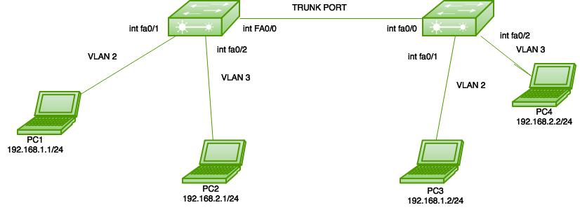
Here is a simple topology in which 2 switches are connected and VLANs 2 and 3 are configured on both switches as shown.
NOTE: as user has not assigned any VLANs to other ports of switches therefore the other ports will be in VLAN 1 by default.
Now, note that the link between the switches has to be configured as trunk port because here more than one VLAN (VLAN 1, 2, 3) frame has to be exchanged between the switches. Now assigning IP address to PC1-12.168.1.1/24, PC2-192.168.2.1/24, PC3-192.168.1.2/24, PC3-192.168.2.2/24.
Now, first user has to make VLANs on both switches:
Switch1(config)#vlan 2
Switch1(config)#vlan 3


Switch2(config)#vlan 2
Switch2(config)#vlan 3
Now, as user has more than one vlan configured on both switches. Therefore, user have to assign the VLANs to their respective ports on Switch1.
Switch1(config)#interface fa0/1
Switch1(config-if)#switchport access vlan 2
Switch1(config)#interface fa0/2
Switch1(config-if)#switchport access vlan 3
Now, configure VLANs on their respective ports on Switch2.
Switch2(config-if)#interface fa0/1
Switch2(config-if)#switchport access vlan 2
Switch2(config)#interface fa0/2
Switch2(config-if)#switchport access vlan 3
Now, configure the link between 2 switches as trunk port.
Switch1#interface fa0/0
Switch1#switchport trunk encapsulation dot1q
Switch1#switchport mode trunk
As a result of this, now user can carry more than one VLAN traffic from one switch to another switch (here, only configuration of switch ports are shown not the configuration of router is shown. To perform inter vlan routing, configuration of router is also needed).
 |  |